


When you start exploring OrcaSlicer, you quickly realize one thing: this slicer doesn’t just apply “magic” profiles. It provides an impressive array of fine-tuning settings, often absent or deliberately simplified elsewhere. This is great news… provided you know when and how to use them.
In this article, we will detail the menus that have a direct impact on visual quality, mechanical strength, and overall print reliability. Line width, walls, seam, infill, supports, or even brim: each setting has a precise logic and, most importantly, interactions with the others.
Quality Menu: where it all begins
The Quality menu can sometimes be approached too quickly. Yet, this is where the details that turn a merely acceptable part into a clean and well-controlled piece are decided.
Line widths: more than just a number
Line width is often confused with nozzle diameter. In reality, it is a slicing decision rather than a strict hardware constraint.
You can set different line widths depending on the context: walls, infill, top or bottom layers. This flexibility opens the door to much smarter settings:
- – A line width slightly larger than the nozzle diameter improves inter-layer adhesion.
- – Strength is also higher when using wider lines.
- – A smaller width better preserves fine details.
- – Variable widths facilitate filling complex areas without creating gaps.
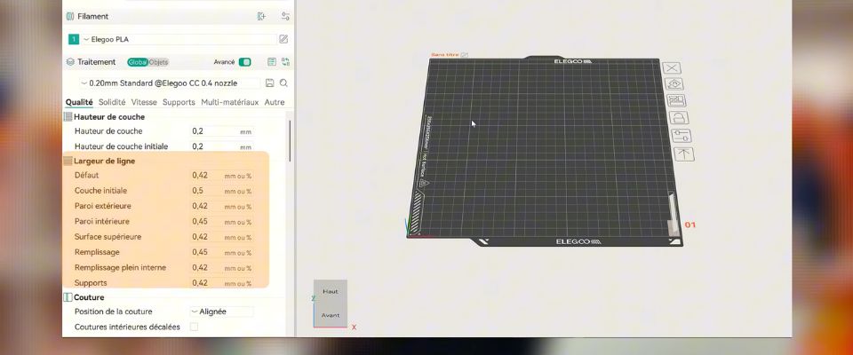
Here we understand that quality does not depend solely on layer height. It equally depends on XY flow management.
Important point: modifying line widths may also require adjusting print settings such as speed or extrusion temperature.
Seam: making the inevitable… invisible
The seam is a necessary evil in FDM. Every layer must start and end somewhere. The real question is not how to eliminate it, but how to make it as invisible as possible.
Several placement strategies exist:
- – Aligned seam for a coherent and more aesthetic finish.
- – Random seam to break visual repetition and avoid creating a large weak area.
- – Hidden seam in corners or concave zones.
The right choice depends largely on the model. A functional part has different requirements than a decorative object. This setting is often underestimated. Yet its use can affect the final appearance, especially on cylindrical surfaces.
Wall generator: classic or Arachne ?
In our software, there are two wall generation logics, each addressing different needs.
Classic mode: robust and predictable
Classic mode uses concentric walls of constant width. It is particularly suited for the following parts:
- – Simple parts with regular shapes and thick walls,
- – Prints where consistency and speed are more important than detail.
It’s a reliable mode, easy to anticipate, and compatible with almost all materials.
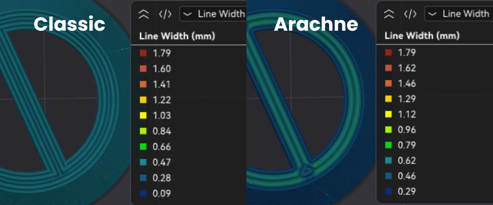
Arachne mode: when geometry becomes complex
Arachne mode radically changes the approach. Here, the slicer dynamically adjusts line widths to fit the actual geometry of the model. This mode optimizes strength.
The benefits are immediate:
- – Better handling of thin walls and complex geometries,
- – Reduced internal gaps with optimized material distribution,
- – Excellent detail reproduction and smooth transitions between walls
This mode is especially relevant for organic models, embossed text, or 3D-scanned parts. It is particularly suited for technical materials requiring perfect fusion between lines.
Advanced Arachne mode settings
These powerful parameters should be used methodically:
- Wall transition angle threshold: defines at which angle a width transition is applied. Too low a value may cause extrusion errors.
- Transition filtering margin: smooths abrupt variations by preventing rapid changes in the number of walls.
- Wall transition length: indicates over what distance the wall variation occurs (longer distances yield smoother and more precise transitions).
- Number of walls affected: specifies how many outer walls can change width, distributing the adaptation across multiple walls.
- Minimum wall width: prevents walls from being too thin and fragile.
- Minimum feature size: defines what is considered printable.
- Minimum wall length: avoids printing unnecessary micro-segments.
Wall printing order: a strategic choice
Printing order directly affects dimensional accuracy, surface finish, and mechanical strength.
- Inside / outside: improves adhesion of inner layers and better support for overhangs from infill. Visual appearance may be slightly compromised (seams visible on the outside, inner walls prioritized).
- Inside / outside / inside: improves inter-layer adhesion, internal cohesion, and external finish. However, overhangs are less supported and slight deformations may appear on thin areas.
- Outside / inside: favors visual appearance, but requires a well-calibrated machine to avoid poor inner layer adhesion.
- Infill first: better support for overhangs, useful for certain functional parts. Use with caution due to risk of part deformation.
Strength Menu: resistance is more than infill
Number of walls: the real pillar of strength
Increasing the number of walls is often more effective than densifying infill. Mechanical stress mainly concentrates on the outer walls.
Four or five well-fused walls usually offer better strength than a poorly connected dense infill.
Alternate extra walls
This option reinforces certain layers alternately. It increases strength and rigidity without significantly increasing print time or filament consumption.
Detect thin walls
Essential for complex models, this setting allows adapting the print strategy to avoid ghost walls or overly fragile sections.
Infill patterns
Infill patterns directly affect strength, mass, and processing time. The choice of infill pattern is inseparable from infill density. At equal density, pattern geometry directly influences stiffness, stress distribution, and overall part strength.
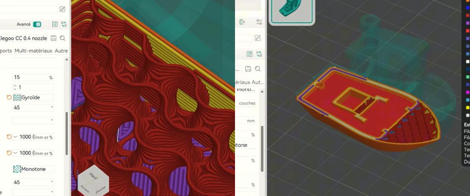
Some patterns prioritize speed and simplicity, while others are designed to optimize mechanical strength, especially for functional parts.
| Infill pattern | Mechanical behavior | Main advantages | Weak point | Recommended use |
|---|---|---|---|---|
| Line | Very limited directional strength | Very fast printing, low material usage | Low overall rigidity, poor mechanical stress resistance | Quick prototypes, visual parts |
| Rectilinear | Good X-Y strength, weak in Z | Good compromise between speed and strength | Anisotropic behavior under multidirectional stress | Simple parts, general use |
| Monotone | Homogeneous layer strength | Regular flow, good dimensional stability | Little mechanical gain compared to rectilinear | Parts requiring stable and consistent printing |
| Honeycomb | Good lateral and overall strength | Excellent strength-to-material ratio | Longer print time than simple patterns | Mechanical parts subjected to repeated loads |
| Tri-hexagon | Very good X-Y stiffness | Stable structure, good lateral force distribution | Lower Z strength than 3D patterns | Flat mechanical parts or laterally loaded parts |
| Cubic | High strength in all directions | Balanced 3D structure, good behavior under complex loads | Higher material use and longer print time | Mechanical parts under multidirectional stress |
| Gyroid | Very homogeneous isotropic strength | Excellent internal cohesion, good stress absorption | Longer computation and print times | Demanding functional parts, high mechanical load |
In practice, a moderately dense optimized pattern often delivers better mechanical performance than a very dense but poorly adapted infill. For technical parts, 3D patterns like cubic or gyroid generally offer the best balance between strength, mass, and print reliability.
Other Menu: brim, small detail, big impact
Often used automatically, the brim deserves consideration. There are different brim types to address different situations:
- – Improve adhesion of small contact surfaces;
- – Stabilize tall prints;
- – Reduce warping on certain materials.
Properly configured, the brim becomes a real reliability tool.
Conclusion: understand before optimizing
OrcaSlicer is not a “plug and play” slicer, and that is exactly its strength. Every setting has a logic, intention, and usage context.
Taking the time to understand these parameters allows for cleaner printing, fewer failures, and a print truly adapted to the part rather than the other way around.
Next, you can go even further with support management, using modifiers, controlling speeds, flow, and advanced calibration. Feel free to tell us in the comments which topic you’d like us to explore further. In 3D printing, quality never comes from a single setting but from the balance between them all.
✅ Why Choose Polyfab3D?
Premium Support and After-Sales Service: Starting from your needs, we will guide you to the most suitable solution and provide long-term support for its implementation and daily use.
Official Reseller: Polyfab3D is a certified reseller of top brands, ensuring you get official products, exclusive access to the latest innovations, and priority technical support.
Fast Delivery and Customer Satisfaction: Polyfab3D is committed to providing you with an optimal and fast experience. Positive feedback from our customers rewards us and proves the reliability and efficiency of our service.
Contact us now for a personalized recommendation tailored to your needs, budget, and ambitions.